What are you looking for?

An aluminized heat sleeve that is too small can be difficult to install, compress the protected assembly or damage the reflective layer. A sleeve that is excessively large can move away from the intended heat-exposed area, interfere with surrounding components and make consistent OEM assembly more difficult.
Correct sizing therefore starts with the actual dimensions of the completed component and the way the sleeve will be installed.
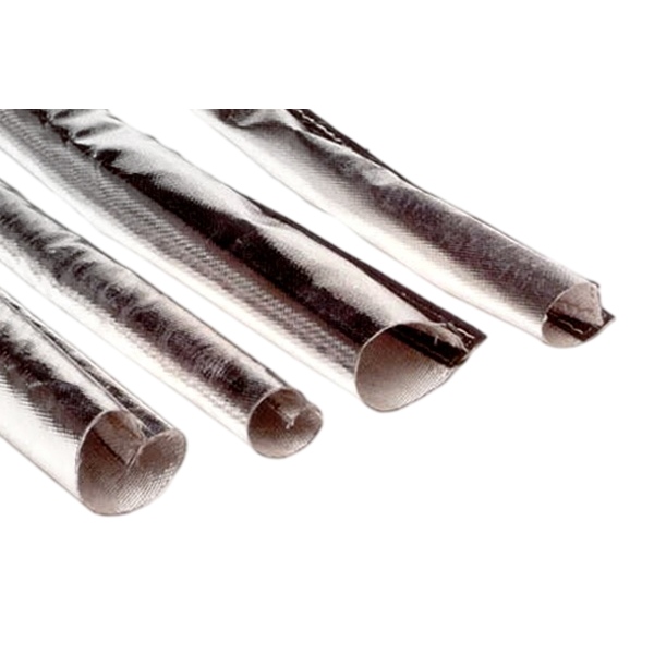
BSTFLEX manufactures aluminized heat protective sleeves for automotive wire harnesses, cables, hoses and fluid lines in tubular, sewn, wrap-around, hook-and-loop, snap-closure and self-closing constructions.
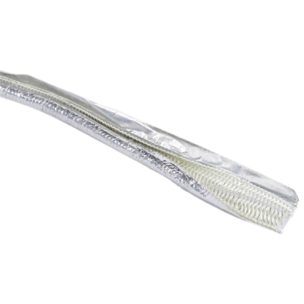
Heat sleeve dimensions can be described in several different ways depending on the construction.
Common dimensional terms include:
These dimensions are not interchangeable.
A tubular braided sleeve, sewn tubular sleeve and wrap-around heat shield may all be described as fitting the same hose diameter while being manufactured from very different starting dimensions.
For most wire harness and hose applications, sizing begins with the outside diameter of the component being protected.
Do not use only:
These specifications describe other aspects of the component and do not necessarily indicate the actual outside diameter that must fit inside the sleeve.
Measure the completed assembly at the exact section where thermal protection will be installed.
A hose may be sold according to its internal bore, but the protective sleeve fits around the outside of the hose.
The finished hose outside diameter includes:
Two hoses with the same nominal inside diameter can therefore require different heat sleeve sizes.
For OEM projects, provide the actual hose OD and tolerance from the hose drawing whenever possible.
A wire harness is not always a perfectly circular bundle.
The harness may contain:
Measure several points along the protected section and record both the normal and maximum bundle dimensions.
If the bundle is strongly oval rather than circular, width and thickness measurements can be more useful than a single estimated diameter.
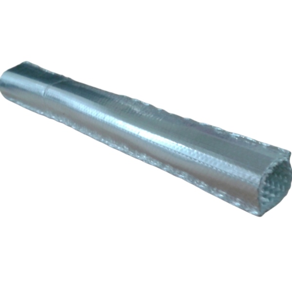
For a slide-on heat sleeve, the largest component that must physically pass through the sleeve can determine the required size.
This may not be the hose or cable itself.
The controlling dimension could be:
Measure these components before selecting a tubular sleeve.
Consider a wire harness with a relatively compact cable bundle but a connector that is significantly wider than the harness body.
If a tubular sleeve is selected only from the harness diameter, the connector may not pass through the sleeve.
Possible solutions include:
The most appropriate solution depends on the OEM assembly sequence and required finished fit.
A tubular heat sleeve requires sufficient clearance to be installed over the protected component.
However, there is no universal percentage that should automatically be added to every component OD.
The necessary allowance depends on:
A rigidly constructed sewn sleeve may need a different dimensional allowance from an expandable braided sleeve.
For critical production applications, select the nominal size from the actual product dimensional table and confirm fit with a production-representative sample.
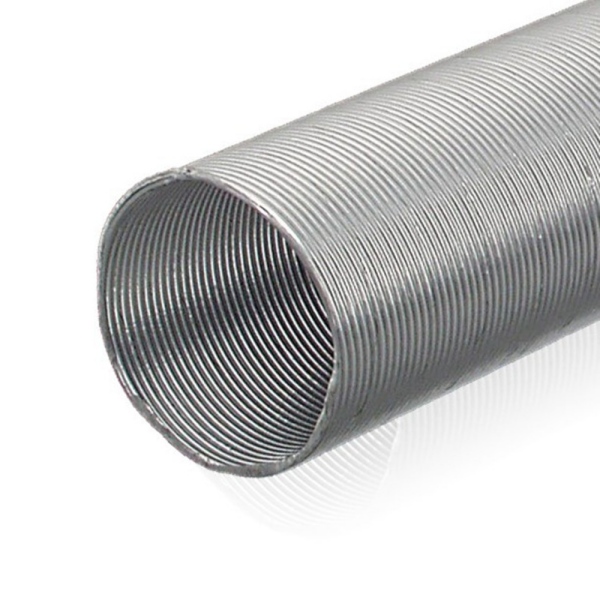
A close fit may appear desirable, but an excessively tight sleeve can create several problems.
It can:
The sleeve should fit securely while still allowing practical installation.
Oversizing can also create problems.
An excessively loose sleeve may:
Sizing should therefore balance installation clearance with positional control.
When measuring an automotive wire harness, record:
| Measurement | Why It Matters |
|---|---|
| Normal bundle OD | Defines the basic sleeve size |
| Maximum bundle OD | Accounts for taped or reinforced sections |
| Connector dimensions | Determines whether slide-on installation is possible |
| Branch-point dimensions | Identifies irregular sections |
| Protected length | Defines finished sleeve length |
| Bend radius | Helps assess sleeve flexibility |
| Clip and bracket positions | Prevents interference with mounting hardware |
For a complete overview of wire harness protection, see Automotive Wire Harness Heat Protection Sleeves: Materials, Designs and Applications.
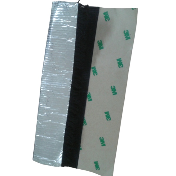
For a hose assembly, measure more than the flexible hose body.
Record:
Where the sleeve must pass over a fitting, the fitting may determine the minimum installation diameter even if the final sleeve is intended to fit a much smaller hose body.
Fuel and brake lines can use flexible hoses, rigid tubes or combinations of both.
For a rigid tube, the outside diameter is usually relatively consistent. For a completed hose assembly, fittings and ferrules can be considerably larger than the main line.
Determine whether the sleeve will:
For fuel and brake line applications, see the BSTFLEX Fuel and Brake Line Aluminum Heat Shield Sleeve.
Coolant and heater hoses can have relatively large outside diameters and complex molded bends.
Measure the hose through the complete protected zone rather than assuming one nominal diameter applies to the entire part.
Pay particular attention to:
A sleeve that fits a straight section may become too tight around a molded bend.
Oil and transmission-fluid lines frequently combine rigid metal tube, flexible hose and crimped fittings.
Each section may require a different sleeve strategy.
A tubular sleeve may be suitable for a straight flexible section, while a wrap-around construction may be easier where the line is already installed or contains large fixed fittings.
Hydraulic hoses require particular attention to fitting dimensions and hose movement.
The protective sleeve should not:
Measure the hose at its maximum working geometry when relevant, not only when the assembly is lying straight on a table.
A slide-on sleeve should be sized according to both the finished component and installation path.
Use the following process:
For production parts, the prototype should represent the maximum expected component dimensions rather than only the nominal size.
A wrap-around sleeve is specified differently because it does not need to slide over the component.
The open material width needs to cover the outside circumference of the hose or harness and provide sufficient overlap for the closure.
For a roughly circular component, the basic circumference can be estimated as:
Circumference = π × Outside Diameter
The finished open width must then also account for:
Therefore, the theoretical circumference alone should not be used as the manufacturing width.
For a custom wrap-around sleeve, send BSTFLEX the actual component OD and required closure type so the finished width and overlap can be developed around the construction.
A hook-and-loop sleeve wraps around the component and closes along a longitudinal seam.
Important dimensions include:
A small amount of closure adjustability may be useful, but the product should not rely on an excessive overlap range to compensate for incorrect sizing.
BSTFLEX offers Aluminized Heat Shroud Sleeving with Hook-and-Loop Closure for completed hoses, cables and wire harnesses.
Snap-closure heat sleeves need enough material width to surround the component while allowing the snaps to align consistently.
The specification should include:
Unlike an infinitely adjustable closure, fixed snaps create defined positions. Accurate dimensional control is therefore particularly important.
See the BSTFLEX Heat Reflective Sleeve with Snap Closure.
A self-closing sleeve uses overlapping edges or an integrated closure structure.
The design needs enough overlap to remain closed around the component throughout its expected dimensional range.
If the component is too large:
If the component is too small:
For this construction, see the BSTFLEX Self-Closing Aluminum Foil Fiberglass Sleeve.
Some flexible sleeves are supplied or inspected in a flattened condition.
The resulting flat width should not automatically be interpreted as the finished inside diameter.
The relationship depends on:
Whenever an RFQ includes flat width, clearly state how that dimension was measured.
If flat width is part of the product specification:
This helps ensure the supplier and customer are using the same dimensional definition.
Sleeve diameter is only one part of sizing. Correct protected length is equally important.
The sleeve should cover the entire thermal exposure zone.
When defining cut length, identify:
A sleeve that terminates inside the high-radiant-heat zone can leave the adjacent component exposed.
A curved hose or harness may require a longer sleeve than the straight-line distance between its endpoints.
Measure along the actual routing path.
This is especially important for:
For component-specific OEM parts, use drawing centerline length or another clearly defined measurement method.
A sleeve changes shape when bent.
Depending on construction, bending may:
A prototype should therefore be evaluated on the actual bent component when the routing includes tight curves.
For hoses and fluid lines, the fitting often controls sleeve installation.
Record the maximum outside dimensions of:
If these components cannot pass through the selected tubular sleeve, a wrap-around construction may provide a more practical solution.
Electrical connectors can be several times wider than the cable bundle.
Before specifying a tubular sleeve, determine whether:
If the connector is located within the high-temperature zone, simply stopping the sleeve before the connector may not solve the complete thermal problem.
Increasing sleeve diameter is not always the correct solution for irregular assemblies.
A large sleeve around a small harness can become loose and difficult to position.
If the assembly includes:
a component-specific shield may provide better fit and thermal coverage.
BSTFLEX manufactures Custom-Shaped Aluminized Fiberglass Automotive Heat Shields for assemblies that cannot be efficiently protected with a conventional straight sleeve.
Heat sleeves installed near exhaust manifolds and turbochargers must remain positioned correctly relative to the heat source.
Oversizing can allow the sleeve to rotate or sag toward the hot component.
Undersizing can compress the protected harness or make installation difficult.
In addition to sleeve dimensions, record:
For this application, see How to Protect Automotive Wiring Near Exhaust Manifolds and Turbochargers.
| Installation Method | Main Sizing Requirement | Common Sizing Risk |
|---|---|---|
| Slide-on tubular | ID must accommodate component and installation path | Connector or fitting cannot pass through |
| Expandable tubular | Expansion range must cover largest installation section | Expansion changes length or fit |
| Sewn tubular | Finished ID and seam tolerance | Insufficient installation clearance |
| Hook-and-loop wrap | Component circumference plus designed overlap | Too little or excessive overlap |
| Snap closure | Closed circumference and fixed snap position | Snaps cannot align around component |
| Self-closing | Component size must remain inside usable overlap range | Seam opens or sleeve becomes loose |
| Custom-shaped shield | Multiple component dimensions and geometry | Using one diameter for an irregular part |
For OEM production, nominal dimensions alone are not sufficient.
Consider component tolerances.
If the hose, harness or fitting has a dimensional production range, test the sleeve against the maximum expected assembly where installation clearance is critical.
Also evaluate the minimum expected component where sleeve looseness or rotation is a concern.
The heat sleeve itself also has manufacturing tolerances.
Potential sources of variation include:
Customer drawings should identify which dimensions are critical to installation and which dimensions can use standard manufacturing tolerances.
Two heat sleeve products described with the same nominal diameter may not have identical usable internal space.
Differences can result from:
When replacing an existing part, provide the actual component dimensions and, where possible, an original sample rather than relying only on another supplier's nominal size designation.
For an existing part, measure:
Also identify the component OD and thermal environment. A replacement should be selected according to function, not only copied dimensionally.
The correct supply format depends on how the customer installs the sleeve.
Suitable when the customer cuts sleeve length during harness, hose or equipment assembly.
Suitable when repeatable installation position and assembly time are important.
Can include cut length, closures, edge finishing, holes, notches, fasteners, labels and packaging according to the approved drawing.
For volume production, a finished component can reduce variation caused by manual cutting at the customer's assembly line.
A useful heat sleeve drawing may include:
The drawing should clearly distinguish dimensions of the sleeve from dimensions of the component being protected.
| Question | Information to Provide |
|---|---|
| What is being protected? | Wire harness, cable, hose, rigid tube or fluid line |
| What is the normal OD? | Measured component outside diameter |
| What is the maximum OD? | Taped section, bend, reinforcement or local enlargement |
| What is the largest fitting? | Connector, ferrule or fitting dimensions |
| How will the sleeve be installed? | Slide-on, wrap-around, self-closing or custom-shaped |
| How long is the heat-exposed zone? | Actual routed protected length |
| Does the component bend? | Bend radius and movement range |
| What is the heat source? | Exhaust manifold, turbocharger, catalytic converter, EGR or other source |
| How much clearance is available? | Minimum distance and installation envelope |
| Is service access required? | Removable or permanent design |
| What quantity is required? | Prototype, batch and estimated annual volume |
The sleeve fits around the outside of the hose, so hose ID does not define the required sleeve ID.
The selected tubular sleeve fits the hose but cannot pass over the crimp ferrule or connector.
The sleeve fits the main harness but becomes too tight around a branch or taped splice.
The sleeve installs easily but moves away from the heat-exposed zone during vehicle operation.
The sleeve fits on a straight sample but wrinkles, compresses or opens when installed on the actual curved component.
The supplier and customer use different dimensional definitions, resulting in an incorrectly sized component.
The prototype fits the nominal assembly but cannot accommodate normal production variation.
BSTFLEX manufactures reflective heat protection sleeves for automotive wire harnesses, cables, hoses and fluid lines.
Customization can include:
For general aluminized sleeve selection, visit the BSTFLEX Aluminized Heat Protective Sleeve category.
For material-specific information, see Aluminized Fiberglass Sleeve for Automotive Wire Harness Protection.
For choosing between tubular and removable constructions, see Slide-On vs Wrap-Around Heat Protection Sleeves for Automotive Wire Harnesses.
For an OEM quotation, send BSTFLEX the protected component dimensions, connector or fitting dimensions, required sleeve length, heat-source information, installation method, drawing or photographs, prototype quantity and expected annual volume.
Measure the actual outside diameter of the hose, cable or wire harness at the protected section. Then check the largest connector, fitting or branch that the sleeve must pass over and select the sleeve according to its construction and dimensional table.
Not necessarily. The sleeve needs practical installation clearance, but the required allowance depends on sleeve flexibility, wall construction, component geometry, length and installation method. There is no single percentage that applies to every heat sleeve.
Measure the hose outside diameter because the heat sleeve is installed around the exterior of the hose.
Measure the maximum fitting or ferrule outside dimension. If the selected tubular sleeve cannot pass over that dimension, install the sleeve before fitting assembly or select a wrap-around, self-closing or other openable construction.
Measure both the normal and maximum wire-bundle dimensions. Also measure connectors, branch points, taped sections and other local enlargements that may affect installation.
Flat width is the width of the sleeve when laid flat. It is not automatically equal to the finished inside diameter. The relationship depends on the sleeve construction, material thickness and seam design.
For a roughly circular component, circumference can be estimated as π multiplied by component outside diameter. The actual open sleeve width must also include the required overlap, seam construction, wall thickness and manufacturing allowance.
It should fit securely but should not be excessively tight. Too little clearance can make installation difficult and reduce flexibility, while excessive clearance can allow the sleeve to shift or rotate.
Yes. Inside diameter, flat width, open width, cut length, closure design, insulation layers, notches, fasteners and other dimensional features can be customized according to the component and drawing.
Send the component outside diameter, maximum local diameter, connector or fitting dimensions, required protected length, bend information, heat-source location, installation method, available clearance and estimated quantity.

No.10, Chuangxin North Road, Nanshan Park, Ningguo Economic and Technological Development Zone, Ningguo City, Anhui Province, China
Tel/Whatsapp : 0086-15856303740
Email : sales@bstbraidedsleeve.com
Skype : vanesa-cheng